Pressure in the system continuously decreases
no Vent closed after filling and bleeding the system? – (fig. 1) | |
| yes |
|
yes Solar liquid escaping from safety valve? (recommended working pressure 3 bar) | |
| no |
|
no Solar circuit leakproof? “Feel” every soldering point and screwed connection with the fingers | |
| |
- The better the system is vented when filled the lower will be the number of faults caused by air in the system.
- The system is vented by pumping the solar liquid through the system and through a tank filled with the same liquid until no more bubbles come out.
- Pressure variations of 1–2 bar due to temperature variations during system operation are normal.
- The system pressure should not decrease below the value of the static pressure + 0.5 bar, as otherwise a partial vacuum could be created in the upper area of the solar system and air may be drawn in.
The sun is shining but the pump is not running
no Is display on controller visible or does LED light up? | |
| yes |
|
yes Maximum store temperature reached? | |
| no | Check maximum temperature. Recommended:
Change if necessary |
yes Does pump run after switching on manual switch? | |
| no |
|
yes Does controller switch pump? | |
| no | Pump blocked!
If there is no effect, replace the pump |
| Controller defective. Send it to manufacturer. | |
Other reasons:
- The store is hot, but below the maximum temperature. The sun’s radiation is not sufficient to reach the switch-on temperature difference. The behavior of the system in this case is satisfactory.
Temperature difference between collector and storage tank very high
no Is solar circuit pump running? | |
| yes | Has tank reached its maximum temperature?
If yes, behaviour is normal. Otherwise, check controller setting and correct if necessary |
no Does flowmeter show a flow? | |
| yes |
|
no Is volumetric flow suitably high?
| |
| yes |
|
yes Return temperature almost the same as feed temperature? | |
| no |
|
Temperature difference:
- High flow systems: Δt = 10 K
- Low flow systems: Δt = 30 K
Pump running but flowmeter shows no flow rate
no Are all shut-off elements open? | |
| yes |
|
yes Is a flow displayed? ( fig. 1) | |
| no |
|
yes Dirt trap blocked? | |
| no |
|
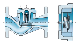
yes Return – flow preventer blocked? (Recommended use of return-flow preventers with springs) fig. 2 | |
| |
The procedure for bleeding the solar circuit is as follows (because of the risk of vapour formation in times of high solar radiation this should be done if possible in the early morning or late afternoon):
- Open all vents.
- Increase system pressure with the help of a filling pump.
- Operate solar circuit pump with brief pulsating movements at maximum capacity.
- If necessary undo screw on recirculating pump, let air out and close again.
- Close all vents after successful bleeding.

Storage tank cools too much overnight without hot water consumption
yes Solar circuit pump running at night? | |
| no |
|
yes Collector temperature higher than outside temperature at night? | |
| no |
|
yes Thermal insulation of tank sufficient? (Min. 100 mm flexible foam, 70 mm rigid foam) | |
| no |
|
no Does thermal insulation fit closely to tank? | |
| yes |
|
no Are all connections thermally insulated? | |
| yes |
|
yes Circulation pump running too long? | |
| no |
|
yes Switch off circulation pump and close shut-off valve for a night | |
| no |
|
- Gravity circulation in circulation line is too strong. Install stronger return-flow preventer or electrical two-way valve after circulation pump.
- Two-way valve open during pump operation, otherwise closed.
- Connect pump and two-way valve in parallel electrically. Start circulation again.
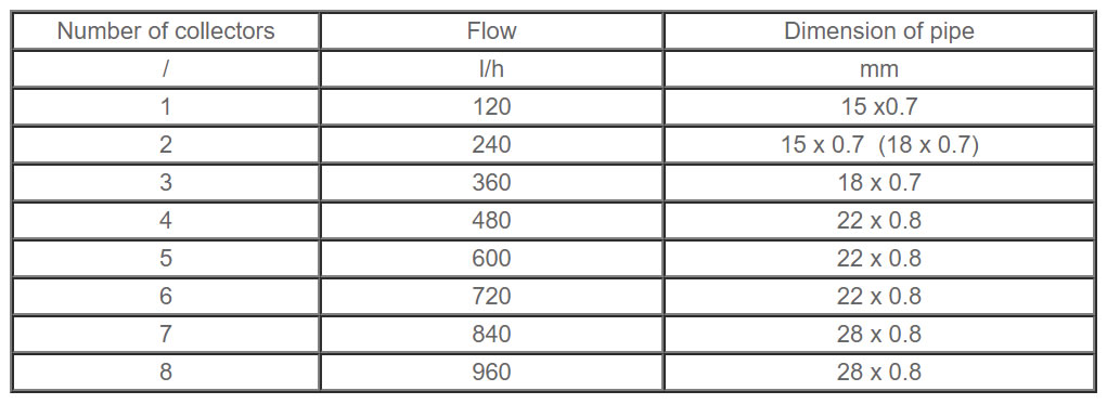
System functioning normally, but the temperature in the storage tank is low
no Does solar circuit is well dimensioned? (table. 1) | |
| yes |
|
no Are the pipes good and fully insulated? | |
| yes |
|
yes Insulation exposed to external influences is damaged (it is recommended to be coated with aluminum sheet). | |
| no |
|
no Are all connections thermally insulated? | |
| |
Protection from overheating and stagnation temperature
According to European standard EN 12976, solar thermal systems shall have been designed in such a way that prolonged high solar irradiation without heat consumption does not cause any situation in which special action by the user is required to bring the system back to normal operation.
The system can be protected against overheating in one of the following ways:
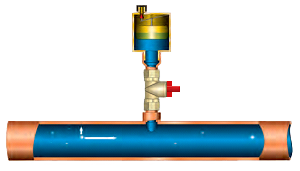
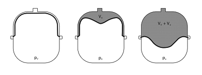
- The storage tank has reached the maximum temperature of 60оC, but still there is solar radiation. By stopping the collector pump and letting the collector fluid boil in the collector until it is dry and heats up to its stagnation temperature. The fluid is expanded into a suitable expansion vessel. Here it is important that evaporated solar medium cannot escape from an automatic air bleeder. A valve beneath the air bleeder can prevent this.
The picture shows the situation where fluid in conditions of stagnation would reach boiling point, which depends upon the pressure of the system.
The expansion vessel must be large enough to take the volume of liquid displaced from the collector due to evaporation, as otherwise the system would release the pressure via the safety valve and the system pressure would reduce too quickly after cooling. The response pressure of the safety valve should be 6 or 8 bar.
- Calculation of the membrane (closed), expansion vessel:
First determine the volume of the system:
VA = VIT + VP + VK + VCM
VIT – exchanger
VP – circulating pump
VK – collectors
VCM – solar circuit
Preset pressure of vessel (bar) is calculated by the following formula:
P0 =(hstat/10) + Pd
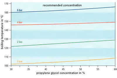
Pd – pressure of the glycol steam
hstat – static height of the collectors
The required nominal volume of the expansion tank is:
Vn,min = (n × VA + VK + 0.1 × VCM) × (Pe +1)/ (Pe – P0)
Pe – final pressure in the expansion
Pe = 0,9 x Psv
Psv – pressure on which safety valve responds
The above operating condition means that the solar energy system is put under a certain stress. In other words, if the evaporated condition happens too frequently the heat transfer medium will age more rapidly.
In order to avoid this load, or to reduce it, the following measures can be used:
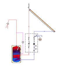
- In small and large systems, such as initial protection against stagnation we can use non isolated pot in which condenses steam formed in the initial phase of stagnation. The pot is placed on the expansion of the pipe under the automatic air valve on top of the collectors ( Fig. 1)
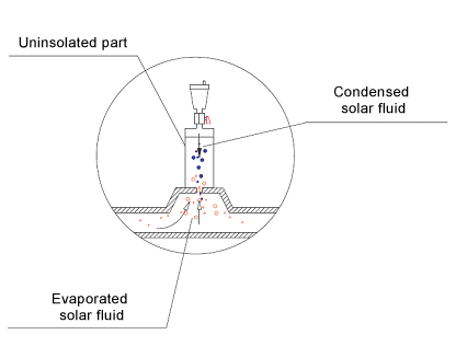
Fig. 1 - By putting the collector at a steeper tilt angle, not only are the amount of excess heat and the stagnation times over the summer period reduced, but the yield in the winter is also increased.
- During holidays and annual vacations return-flow preventers are opened or pump run continuously day and night (regulated by means of digital differential automation). In this way the solar store can discharge via the collector at night- extra consumption of electricity.
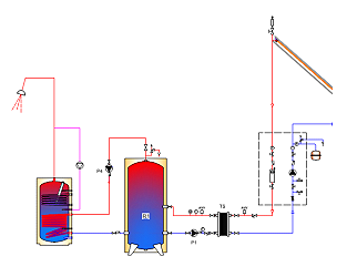
- . In drainback systems, by stopping the circulation pump so that the collector is drained. The fluid is drained in additional drain back tank. (Fig. 2)
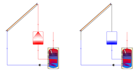
Fig. 2 - If possible, the excess heat is used to heat the swimming pools, etc. If it is not possible, then excess heat is referred to heat exchanger (radiator, towel radiator, copper coil, fancoil etc.) that is located under roofing, in the basement or heat is referred to another medium, for further exploitation.